LIMNMEDIA - Upright Mounting & Spacing Constraint
This set shows the final layout and drilling of the upright mounting pattern, followed by the installation of the full boom and upright assembly onto the base plate.
This stage shows the final layout and drilling of the upright mounting pattern, followed by installing the full boom and upright assembly onto the base plate. It’s a satisfying step because the structure finally stands as a single unit—but it’s also the moment where a subtle design decision becomes very obvious.
What looked clean and efficient earlier begins to reveal its limitations once everything is physically assembled.
Process
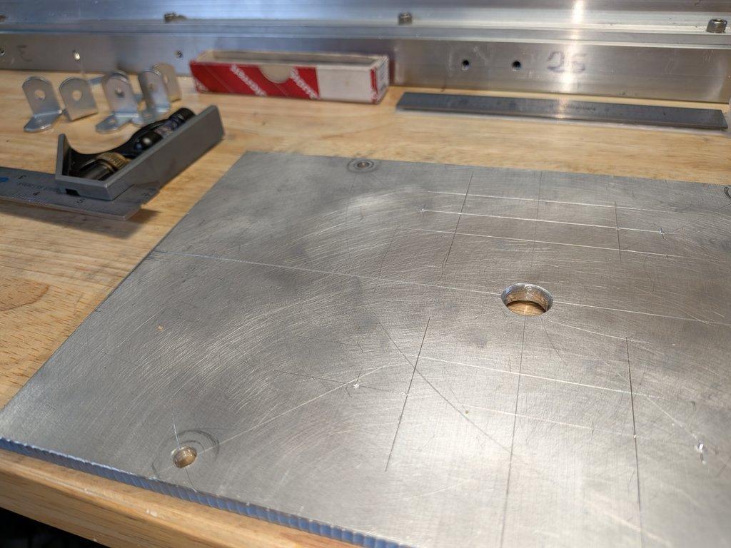
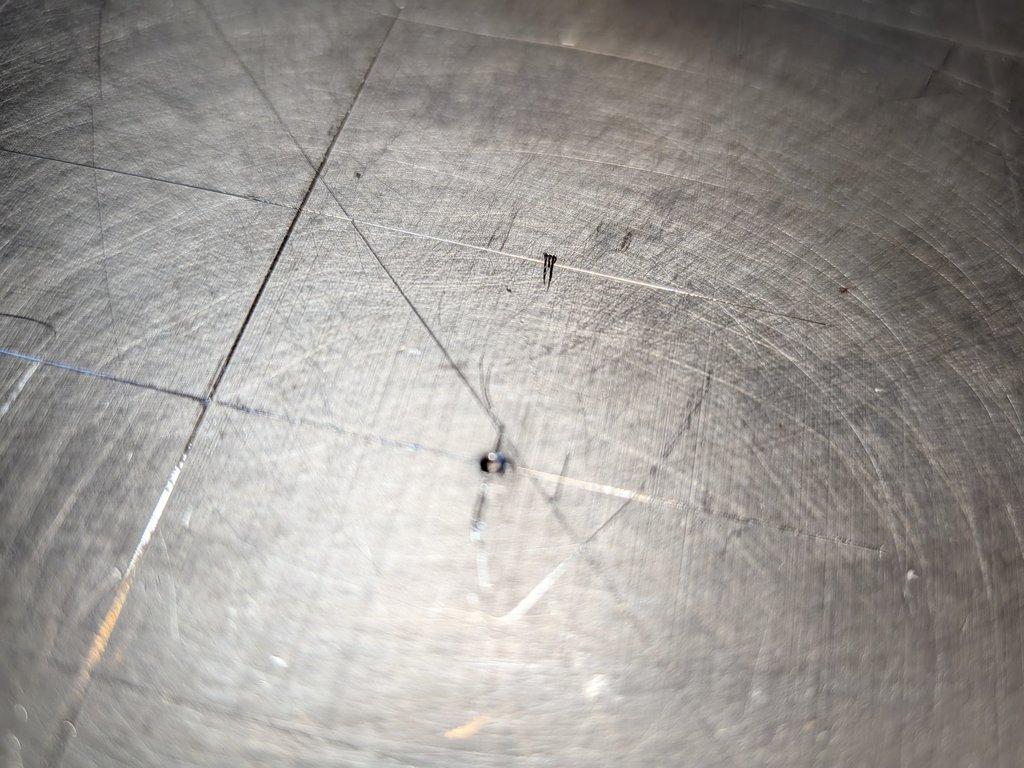
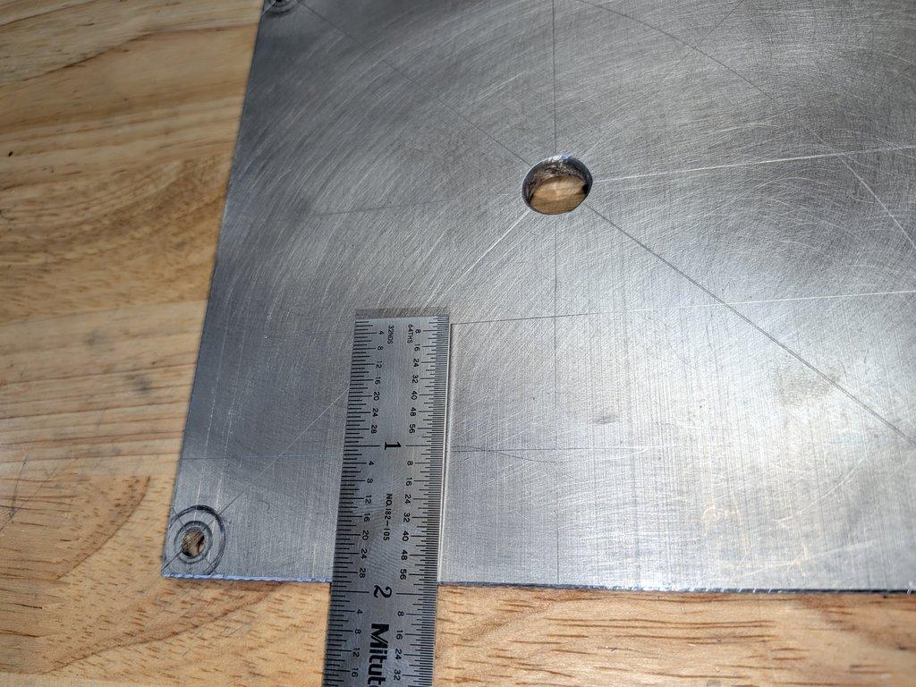
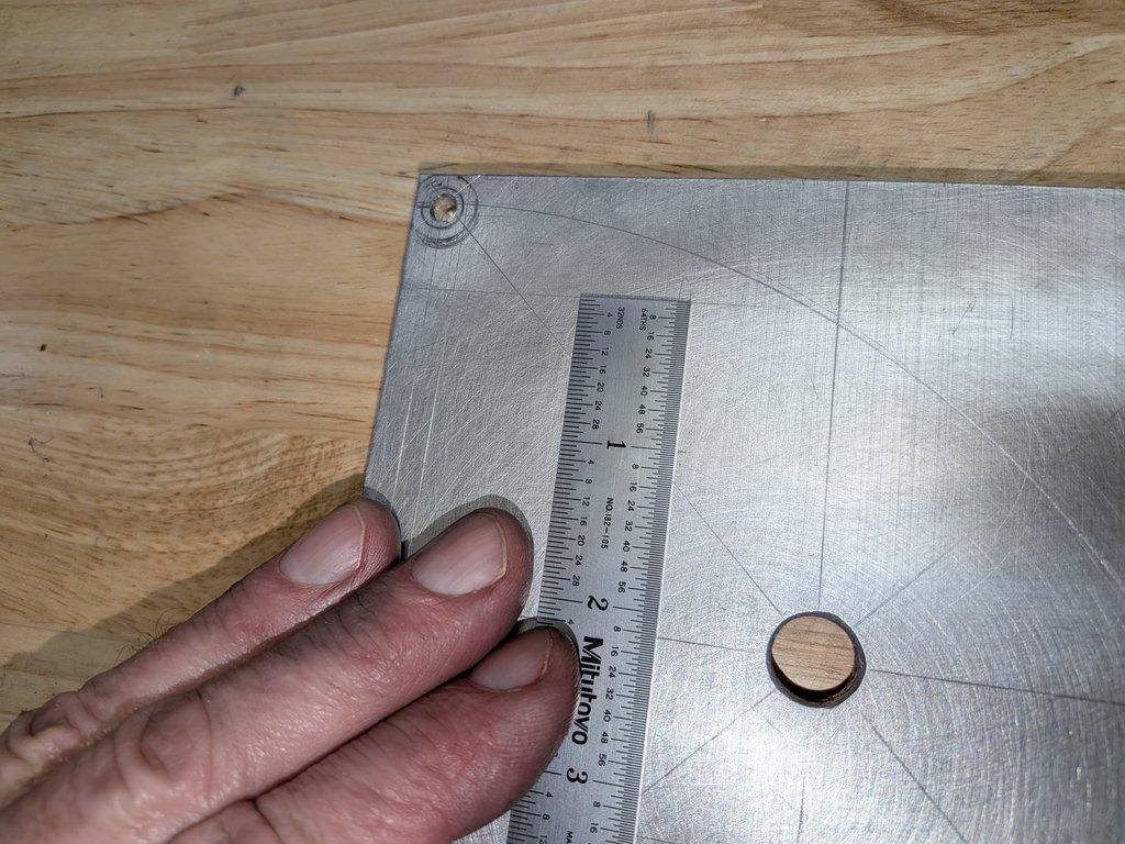
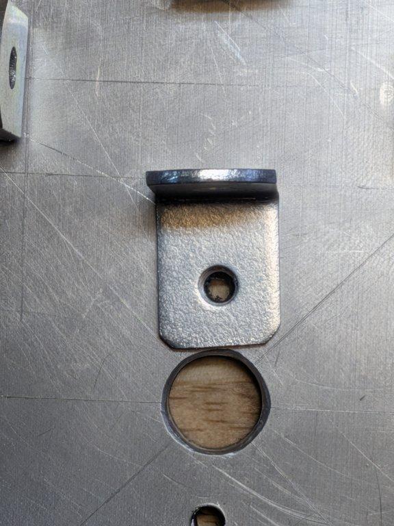
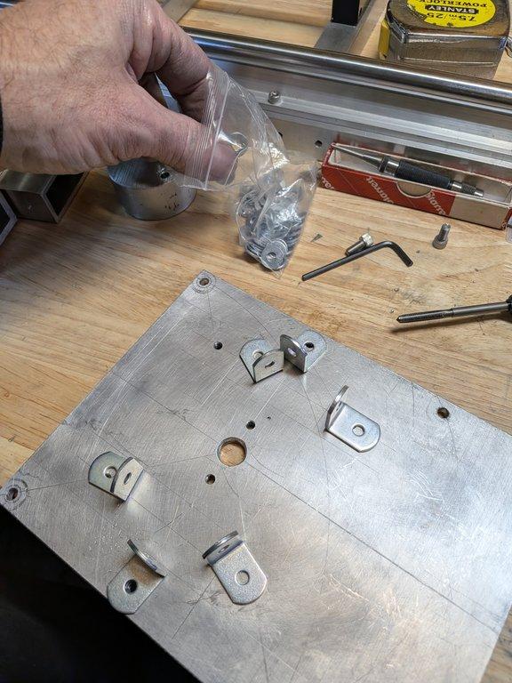
After completing the layout, the mounting holes for the uprights are drilled into the base plate. With those in place, the uprights are secured and the boom assembly is installed, bringing together several previously separate parts into a single working structure.
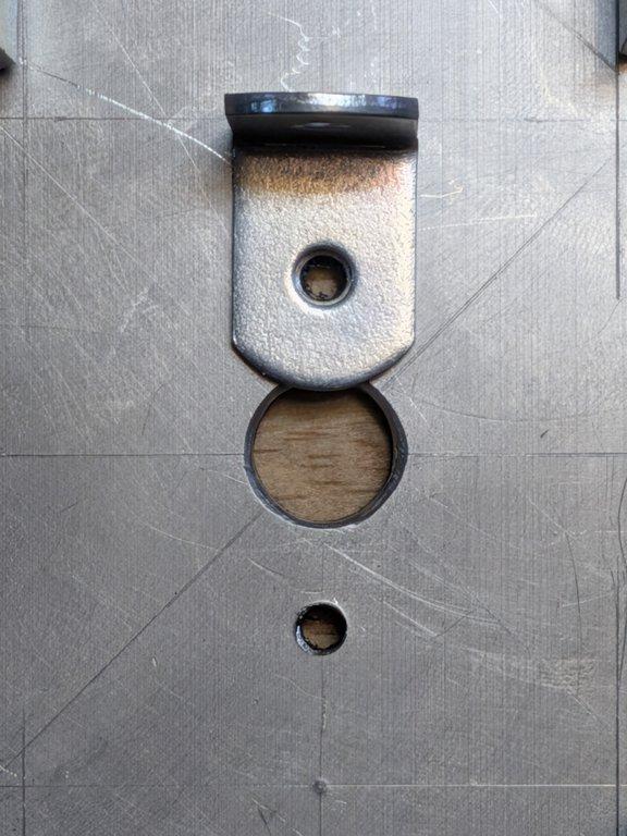
During this process, the center angle bracket needed adjustment. At this stage of a prototype, small corrections are part of the workflow. Getting everything to sit square and align properly requires a bit of iteration, even if the layout was carefully planned.
With the pivot shaft installed, shaft collars are added on the outside of the bearings. This is a nice, clean solution for retaining the shaft. It’s easy to access, easy to adjust, and mechanically it works well. But it also highlights something that wasn’t fully apparent until now.
Notes
The decision to mount the boom bearings on the outside of the uprights felt like a straightforward one. It simplified assembly and made the system feel accessible and serviceable. In isolation, it’s a reasonable choice.
But when everything comes together, that choice pulls the uprights closer together than ideal.
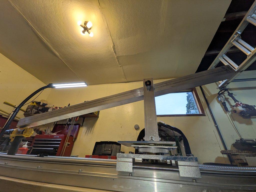
At first, it’s just a feeling—something looks a little tight. Then it becomes measurable. The space between the uprights is reduced in a way that starts to limit options. There’s less room for the boom structure, less clearance for future drive components, and less flexibility overall.
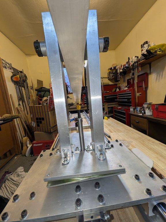
At the same time, the shaft collars sitting on the outside are doing exactly what they should. They’re secure, visible, and easy to work with. So the design isn’t “wrong.” It’s just carrying a consequence that only becomes visible at this level of assembly.
The adjustment to the center angle bracket is part of the same story. Even when individual parts are made carefully, the moment they’re brought together, the system reveals where it needs to be nudged into alignment. There’s a difference between parts being correct on their own and parts working together as a system.
Context
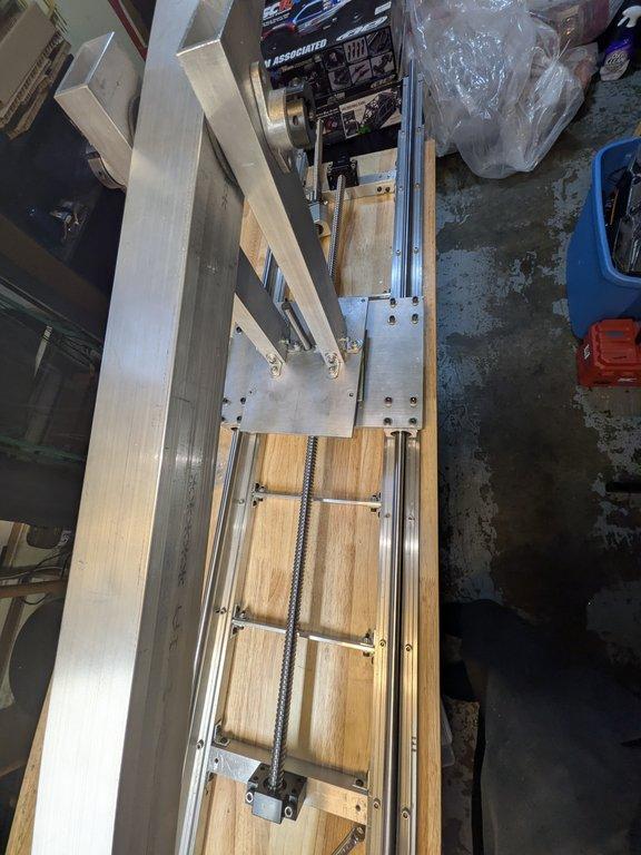
This is one of the first moments where the crane begins to feel real. The base, uprights, and boom are now physically connected, and the relationships between them are no longer abstract. You can see how the arm sits, how the structure holds itself, and how the geometry begins to define motion.
It’s also the moment where the build starts pushing back.
Up to this point, the design has been guided by intention—keep things tight, keep things efficient, minimize excess. But now the physical system is responding to those choices. Tight tolerances and minimal spacing reduce forgiveness. They leave less room for adjustment, less room for variation, and less room for future additions.
Why This Matters
There’s a particular kind of clarity that only comes from assembling real parts. On paper, everything can feel aligned and logical. In practice, the system reveals how those decisions interact.
Placing the bearings outside the uprights solved one set of problems. It made assembly easier. It made shaft retention straightforward. But it also introduced a constraint that wasn’t obvious until now—the uprights are closer together than they need to be.
This is the nature of prototyping. Every decision carries forward, and some of those consequences only show up when enough of the system exists to make them visible.
It’s not a mistake so much as a discovery.
And this is where the mindset matters. The goal here isn’t to arrive at a perfect design on the first pass. The goal is to understand the system well enough to make better decisions on the next pass.
This is still the skateboard, not the Ferrari.
Christopher Weinberg
Christopher Weinberg is the founder of LIMNMEDIA, where he develops motion control systems, production workflows, and educational tools focused on stop-motion and hybrid filmmaking. With over 15 years of experience in production, his work centers on making complex techniques more accessible through practical engineering and open development. He is currently building LIMNMOCO, a modular motion control system designed for flexible, real-world use.
No comments yet. Login to start a new discussion Start a new discussion