LIMNMEDIA - Rotation Stack Assembly
This set of images captures the first look at the full rotation stack coming together.
While it’s a simple moment visually, it represents a major transition in the build—from individual components to a working structural system.
Even without a perfect shot of the bearing itself, the stack clearly shows how the layers interface and establish the crane’s rotational base.
Process
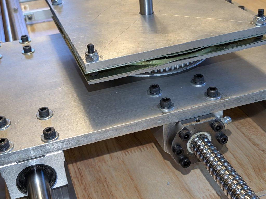
The assembly builds up in layers:
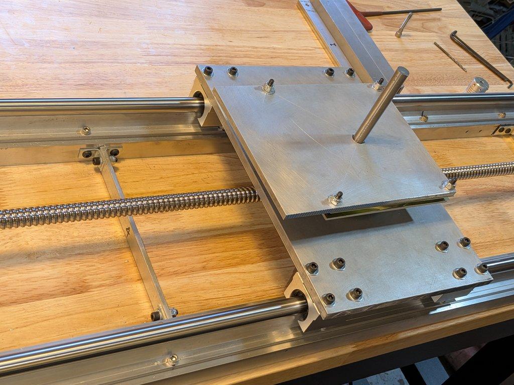
- The sled plate forms the base, riding on the linear rail system
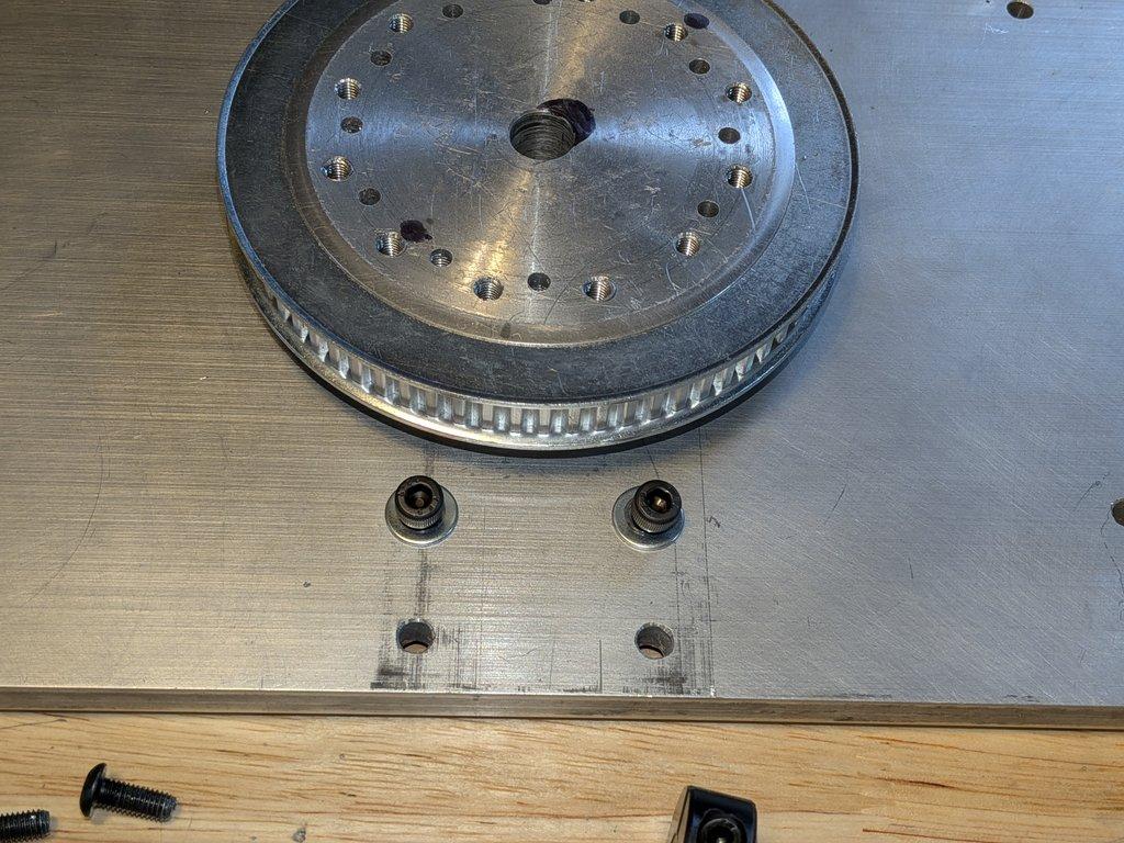
- The 167mm XL pulley mounts directly to that plate
- A thin stainless adapter plate sits on top of the pulley
- The lazy susan-style swing bearing (zinc-coated) is sandwiched above that
- Finally, a larger, thicker aluminum plate mounts to the top of the bearing
That top plate becomes the true base of the crane, where the upright supports and boom drive system will attach.
Notes
The bearing itself isn’t fully visible in detail here, but you can identify it by the different finish—it has that slightly dull, zinc-coated look compared to the aluminum parts above and below it.
What’s important in this moment is not the individual parts, but how cleanly they stack:
- the center axis is shared through the entire system
- the bolt patterns are registering correctly
- the spacing between layers is tight and controlled
The thinner stainless adapter plate is doing exactly what it was intended to do—keeping the vertical distance between components minimal. That decision will matter later when fitting the swing drive pulley and motor, where even small increases in spacing can complicate alignment.
The top plate, being thicker aluminum, establishes a more rigid platform for everything that comes next. This is where structural loads start to increase, so the material choice shifts accordingly.
LIMNMOCO Context
This stack defines the core rotational interface of the entire crane:
sled → pulley → adapter plate → bearing → base plate
From this point forward:
- everything above rotates
- everything below remains fixed to the track
It’s the moment where the system shifts from:
linear motion prototype → multi-axis motion system
Why This Matters
This is the first time all the major rotational components are physically connected. If something were off—hole alignment, center axis, spacing—it would show up here immediately.
Instead, what this confirms is:
- the bolt patterns are working
- the center alignment is holding
- the design decisions around spacing and material are valid
It’s a quiet step, but it’s foundational. This stack is the anchor point for the entire crane.
Christopher Weinberg
Christopher Weinberg is the founder of LIMNMEDIA, where he develops motion control systems, production workflows, and educational tools focused on stop-motion and hybrid filmmaking. With over 15 years of experience in production, his work centers on making complex techniques more accessible through practical engineering and open development. He is currently building LIMNMOCO, a modular motion control system designed for flexible, real-world use.
No comments yet. Login to start a new discussion Start a new discussion