LIMNMEDIA - Driver Wiring & Control System Integration
This set of images shows the wiring and integration of the driver and control system for LIMNMOCO.
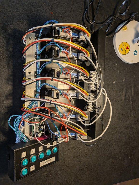
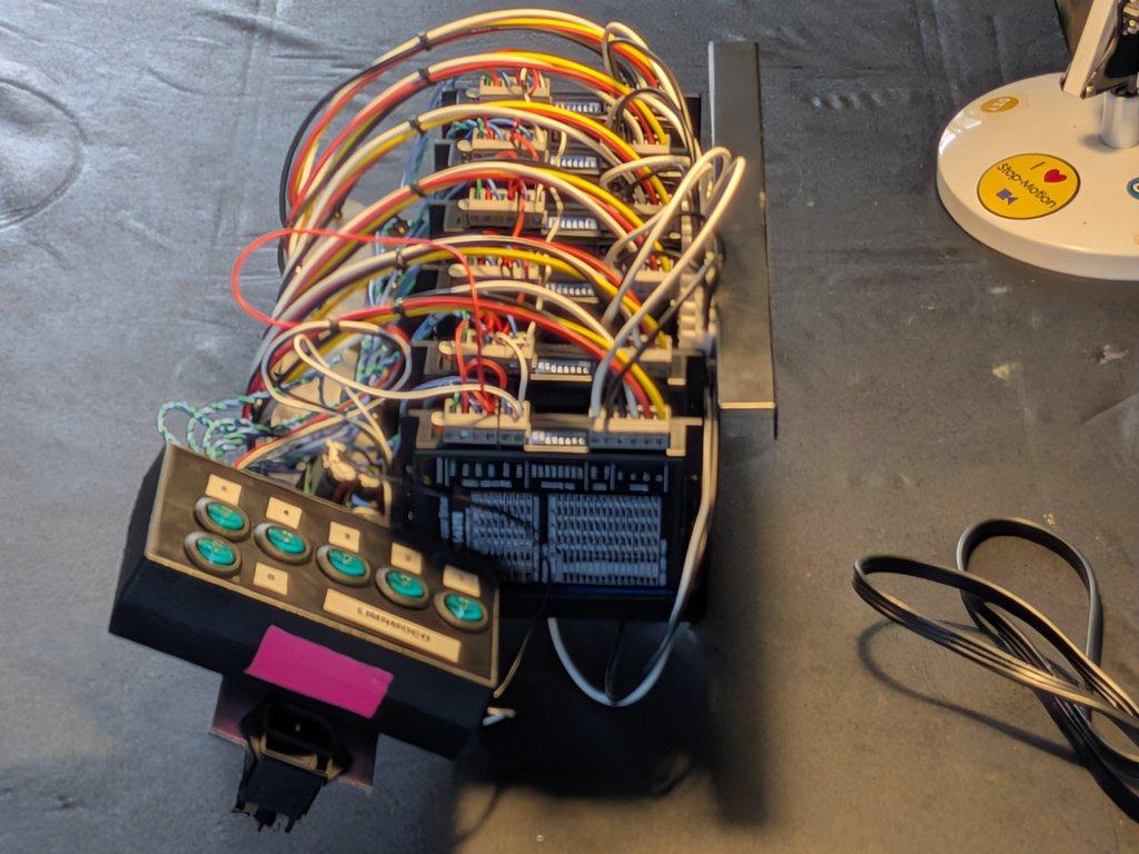
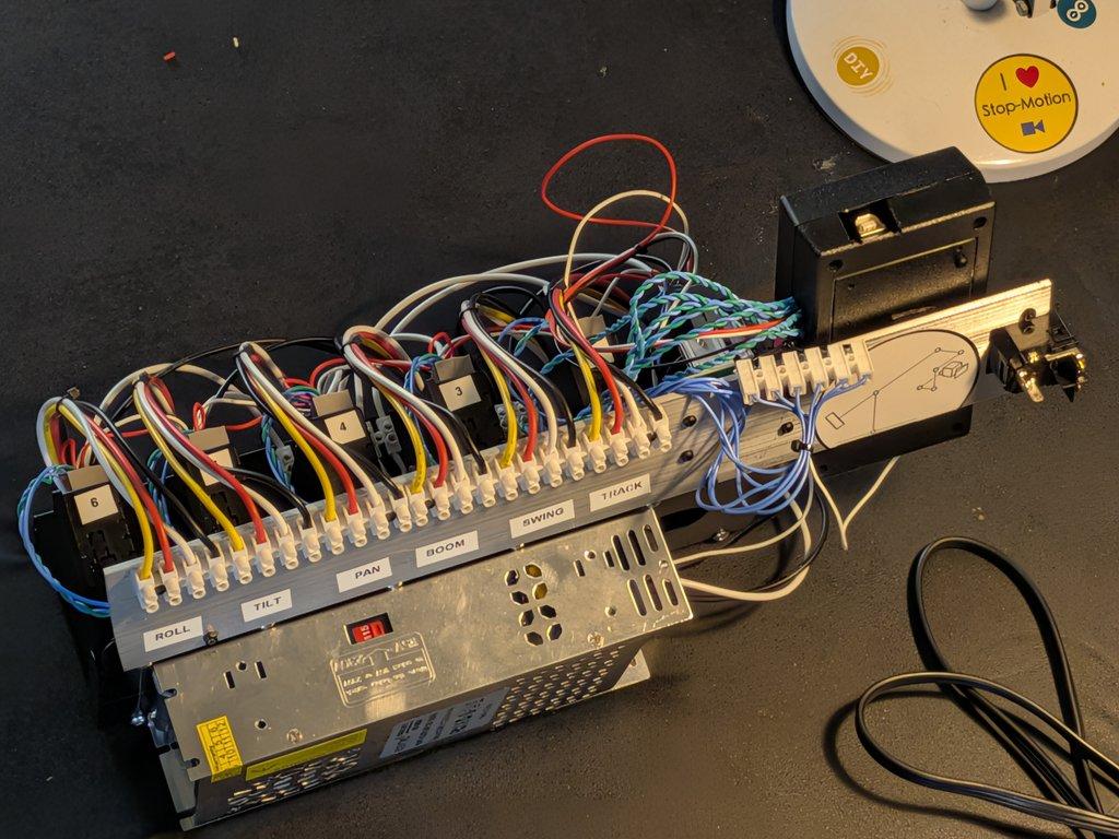
This next set of images shows the driver wiring coming together on the LIMNMOCO stop-motion crane, with six DM542TE drivers being integrated into the system and connected to the Arduino Mega controller.
As the motion control side of LIMNMOCO starts to take shape, the build moves from purely mechanical structure into a combination of electronics, control, and system layout—all working toward repeatable motion for stop-motion and practical filmmaking.
⸻
System Layout
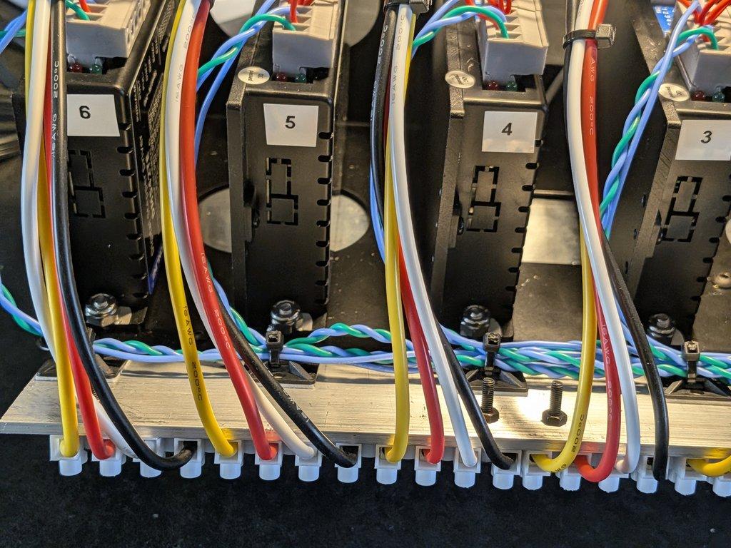
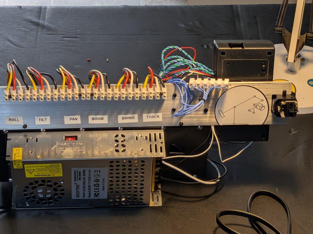
On the bench are six DM542TE stepper drivers, each one corresponding to an axis of the LIMNMOCO motion control crane.
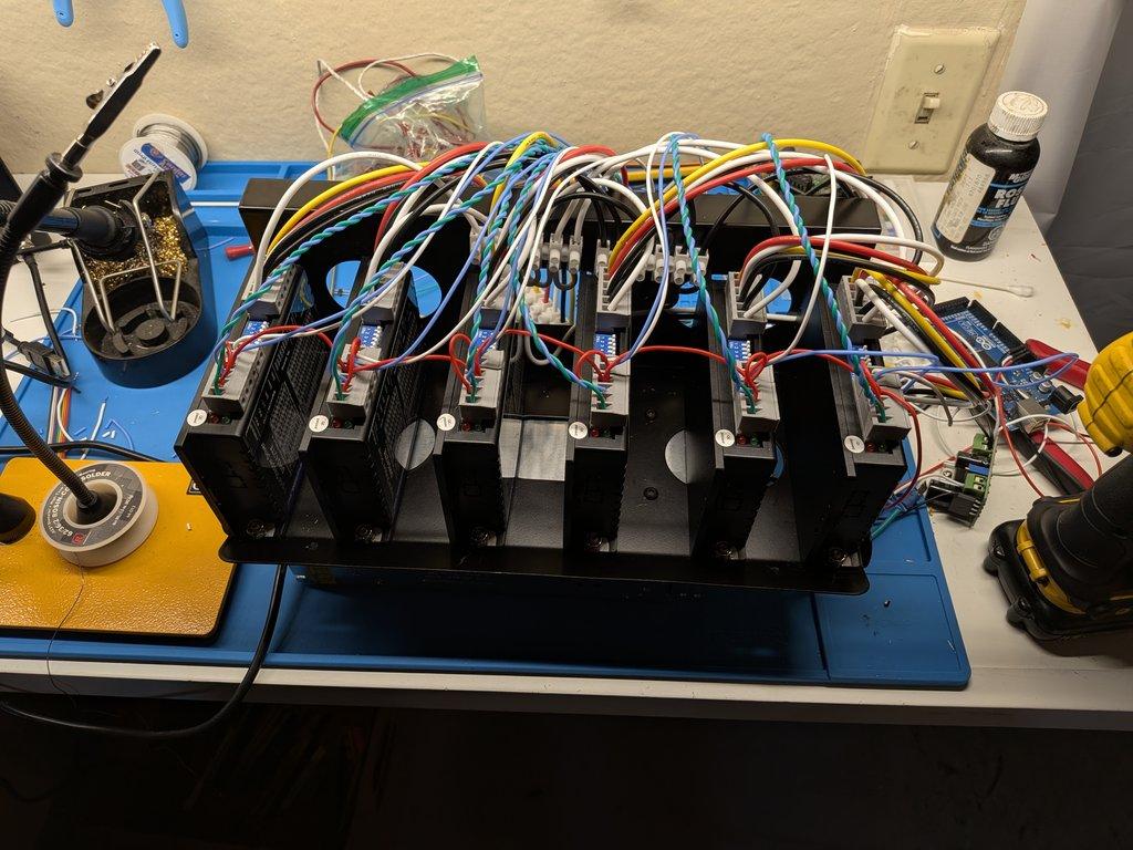
These are paired with an Arduino Mega, which handles the step and direction signals for each axis.
At this stage, the system begins to resemble what it is intended to become: a multi-axis motion control system for stop-motion, where each driver, motor, and control input contributes to a coordinated whole.
⸻
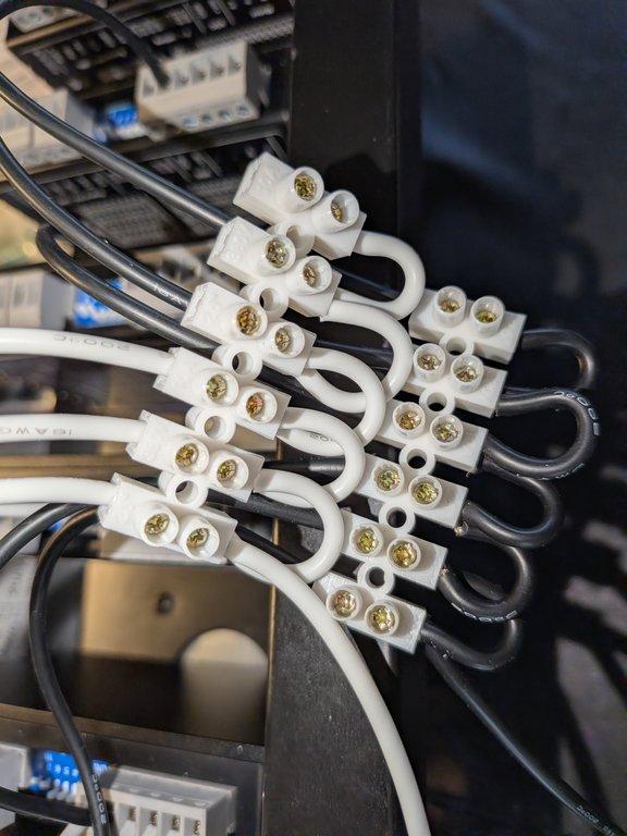
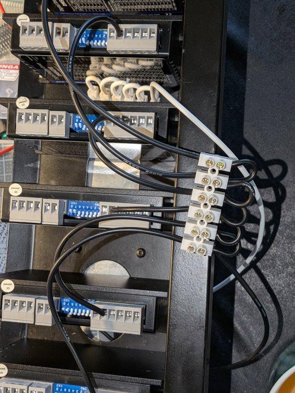
Wiring & Organization
Each DM542TE requires a significant number of connections—power, step, direction, enable, and motor outputs—so with six drivers, the wiring quickly becomes dense.
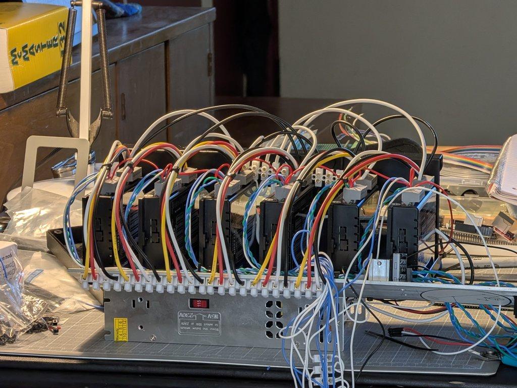
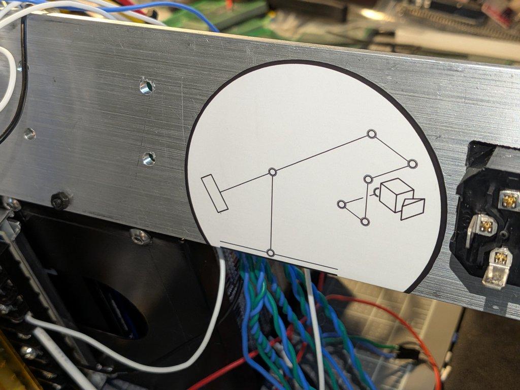
Rather than letting that turn into a mess, I added a strip of aluminum plate along the lip of the bracket to act as a mounting and routing surface for the wiring.
This helps:
- keep the system readable
- provide strain relief
- maintain some level of order as complexity increases
⸻
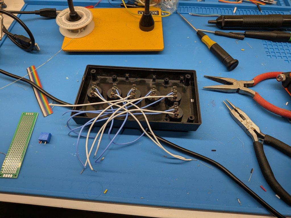
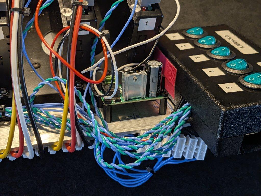
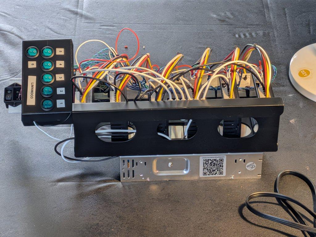
Enable Control (ENA)
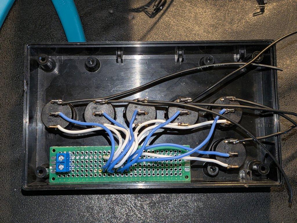
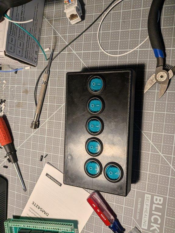
Each driver’s enable (ENA) line is routed through a set of DPST switches with integrated LEDs, mounted in a small control box.
The setup is simple:
- GND for ENA is daisy-chained
- control lines run back to the Arduino Mega
- each switch provides on/off control with visual feedback
This allows individual axes of the LIMNMOCO crane to be enabled or disabled as needed during testing and operation.
⸻
Mounting Approach
The control box is mounted using Velcro, allowing it to be repositioned easily during development.
The power supply is mounted underneath the bracket, with AC input positioned along the edge of the aluminum plate.
The intention is to mount this entire control system under the lip of the workbench—keeping it accessible, but out of the way of the main build area.
⸻
Notes
This is another point where the nature of stop-motion becomes clear.
It’s not just one discipline—it’s mechanical, electrical, and cinematic all at once.
Very few of the components here were designed specifically for a stop-motion crane, but through integration, they become part of one.
⸻
Context
Within LIMNMOCO, this stage establishes the control layer:
- Arduino Mega → logic and timing
- DM542TE drivers → motor control
- switches → user interface
- wiring → system integration
This is what allows the physical structure to become a repeatable motion system for stop-motion cinematography.
⸻
Why This Matters
Repeatability is the foundation of stop-motion.
Without controlled motion:
- alignment breaks down
- multi-pass work becomes unreliable
- precision is lost
This wiring stage is what makes the rest of the system usable.
Christopher Weinberg
Christopher Weinberg is the founder of LIMNMEDIA, where he develops motion control systems, production workflows, and educational tools focused on stop-motion and hybrid filmmaking. With over 15 years of experience in production, his work centers on making complex techniques more accessible through practical engineering and open development. He is currently building LIMNMOCO, a modular motion control system designed for flexible, real-world use.
No comments yet. Login to start a new discussion Start a new discussion