LIMNMEDIA - Drilling & Tapping the 12-Hole Rotation Pattern
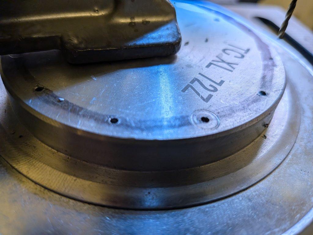
This stage focuses on machining the large diameter XL pulley, which will serve as the base of the crane’s rotation stage.
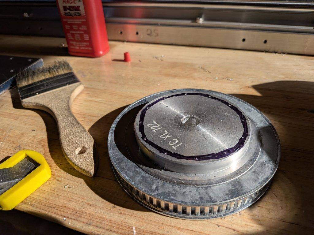
The goal is to establish a precise 12-hole bolt pattern that matches the sled plate and prepares the system for the next layer: mounting a swing bearing.
This is where the layout work from earlier becomes real—translating scribed geometry into permanent, functional mounting points.
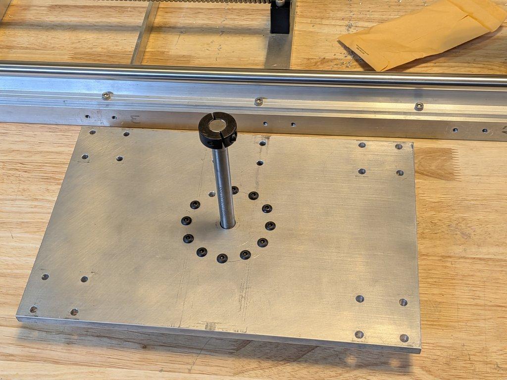
I transferred the bolt pattern from the sled plate to the pulley by first aligning both parts on a shared center shaft, then clamping them securely so nothing could shift. Using the through-holes in the sled plate as guides, I placed a snug-fitting drill bit into each hole and gently rotated it by hand to leave a light mark on the pulley surface. It works, but it’s a bit approximate—you’re essentially estimating the center of that mark afterward. The more accurate approach would be to use a proper transfer or center punch set, which creates a precise divot exactly at the center and removes that guesswork.
Objective
The task here is to drill and tap a 12-hole circular pattern in the pulley so it aligns exactly with the corresponding holes in the sled plate. At the same time, the center bore is used to register everything around a shared axis, ensuring that the entire rotation system stays concentric.
Process
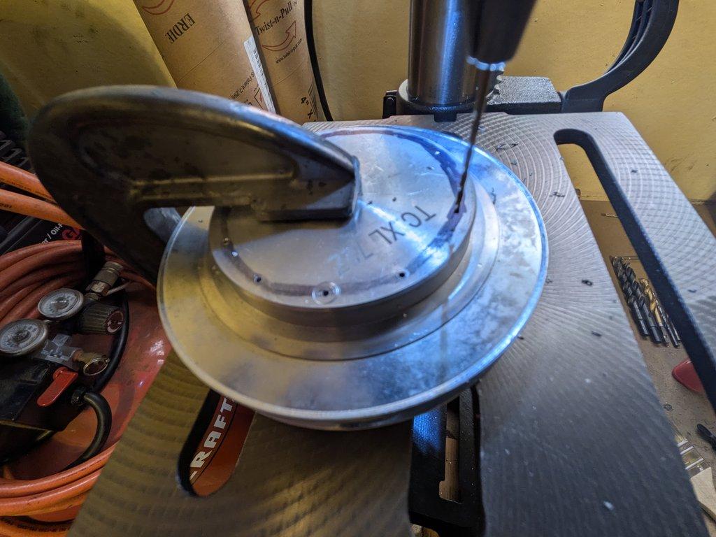
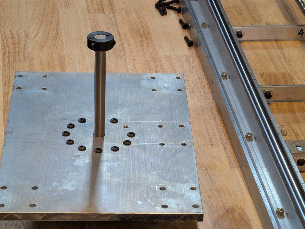
The process begins with drilling pilot holes into the pulley at each of the 12 marked positions around the bolt circle. Taking the time to start small keeps the holes from wandering and preserves the spacing defined during layout.
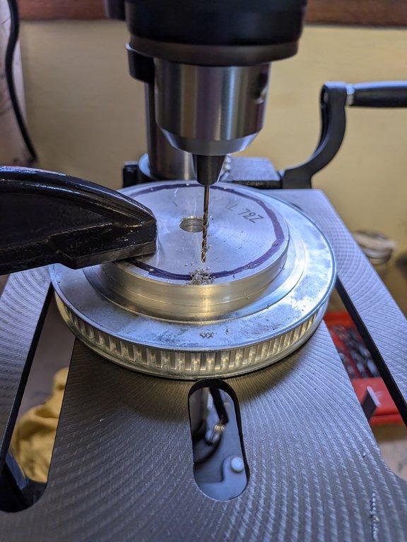
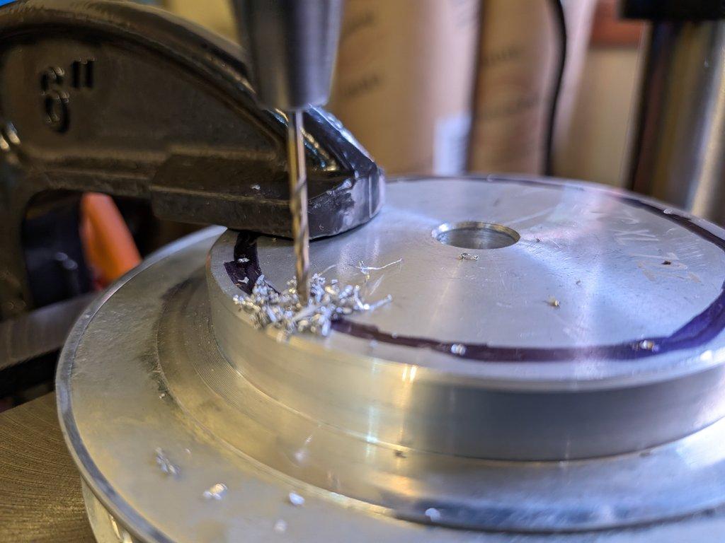
When drilling deeper holes like these, there’s a real risk of snapping the pilot bit if chips aren’t cleared regularly. Aluminum packs into the flutes quickly, increasing friction and heat, which can bind the bit and cause it to break. Back the bit out frequently to clear chips, and use a light cutting lubricant to keep the cut smooth and reduce load on the tool.
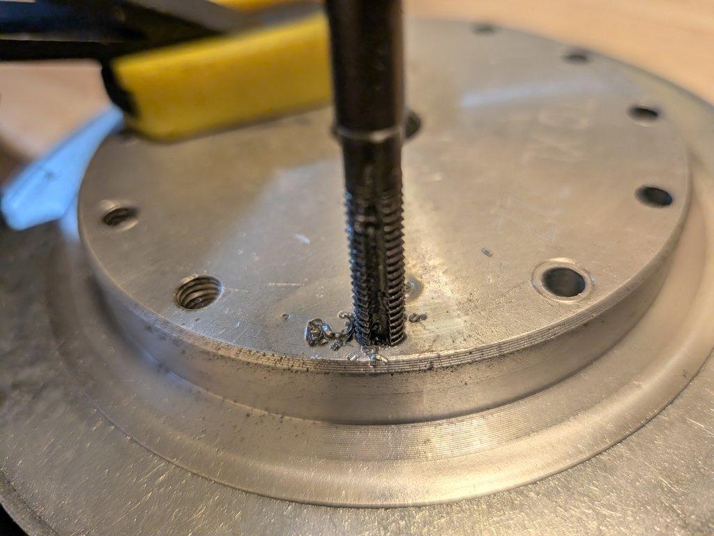
From there, each hole is stepped up to the final size and then tapped by hand. This is slow, deliberate work—especially in aluminum, where it’s easy to move too fast and compromise the threads. Each hole needs to feel consistent, both in resistance and in finish.
Once all 12 holes are complete, the pulley is brought into alignment with the sled plate. A central shaft passes through both the plate and the pulley, acting as the primary reference. With that axis locked in, the 12-hole pattern comes into play, and you can see how everything registers together. The holes line up cleanly, allowing fasteners to pass from the underside of the sled plate up into the pulley.
⸻
Notes
This is one of those operations where everything depends on cumulative accuracy. The bolt circle only works if each step—layout, drilling, and tapping—stays true. Small errors don’t stay isolated; they show up as misalignment across the entire ring.
The center shaft plays a critical role here. It’s not just structural—it’s the reference that keeps the system concentric. Without that, even a perfectly spaced bolt pattern can end up slightly off-center.
There’s also a forward-looking constraint built into this step. This pulley isn’t just mounting to the sled—it’s also going to receive another 12-hole pattern on its opposite face. That second pattern will mount an adapter plate, which in turn will carry a swing bearing, essentially an industrial “lazy susan” that becomes the core of the crane’s rotation.
So the work here has to account for both sides of the part, not just the immediate connection.
⸻
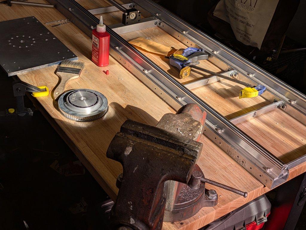
LIMNMOCO Context
This step marks the transition from linear motion components into rotational structure. Up to this point, most of the build has been about rails, sleds, and alignment along a single axis. Now, the system is beginning to define its rotational center.
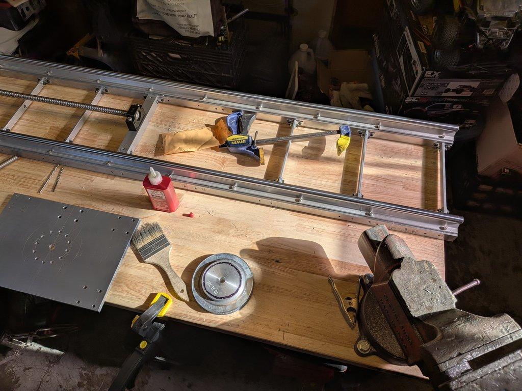
The pulley becomes more than a drive component—it becomes a structural hub. It connects:
- the sled (linear system)
- the future swing bearing (rotational system)
- and eventually the upper crane assembly
Everything starts to converge at this point.
Christopher Weinberg
Christopher Weinberg is the founder of LIMNMEDIA, where he develops motion control systems, production workflows, and educational tools focused on stop-motion and hybrid filmmaking. With over 15 years of experience in production, his work centers on making complex techniques more accessible through practical engineering and open development. He is currently building LIMNMOCO, a modular motion control system designed for flexible, real-world use.
No comments yet. Login to start a new discussion Start a new discussion