LIMNMEDIA - Boom Drive Layout & Base Mount
This set marks the beginning of the boom drive system, starting with the layout of the base mount and the adapter plate that will carry both the linear rail and the motor mount.
Up to this point, the structure has been mostly passive—defined by alignment and geometry. Here, the system begins to take on intentional motion.
This is where the question shifts from “does it fit?” to “how will it move?”
Process
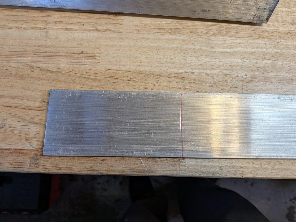
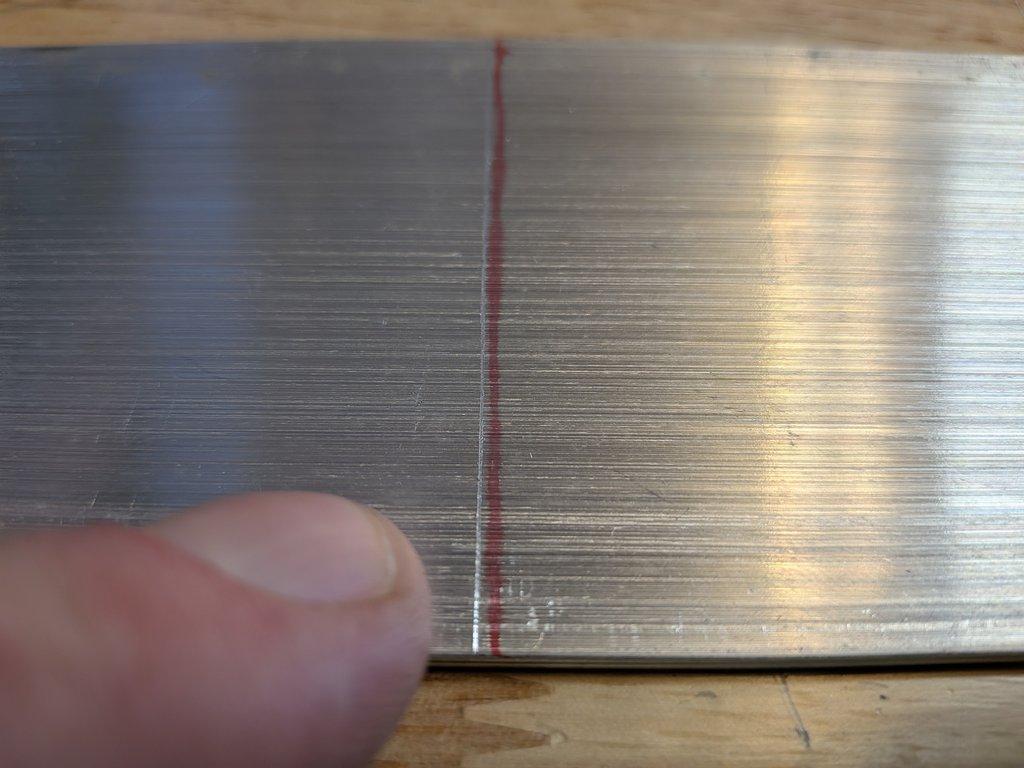
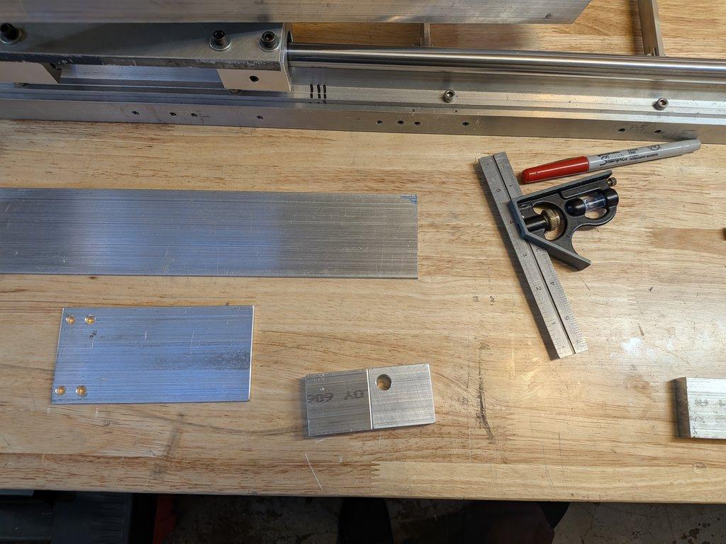
The process begins with laying out the base mounting plate that will support the linear rail. This plate acts as the interface between the structural frame and the drive system, so its placement has to relate back to everything already established—the boom pivot, the upright spacing, and the overall motion path.
An adapter plate is then introduced to bridge between the rail and the motor mount. This allows some flexibility in positioning and helps manage spacing between components. At this stage, the layout is still being worked out directly on the material—marking, checking, and adjusting before committing to final holes.
What’s important here is not just where the parts go, but how they relate to each other in motion. The rail needs to align with the intended direction of force. The motor mount needs to sit in a position that allows for clean coupling. And everything has to coexist within the constraints already revealed by the earlier assembly.
Notes
This stage brings together several competing priorities. The drive system wants clean alignment and space to operate, while the existing structure has already defined certain limits—especially in terms of spacing and access.
The adapter plate becomes a kind of negotiation layer. It’s not just a mounting surface; it’s a way to adjust position, compensate for earlier decisions, and create just enough flexibility to make the system workable.
You can start to feel the difference between designing in isolation and designing in context. Every new component has to respond to what’s already there. There’s less freedom now, but more clarity.
Context
With the base, rotation stage, uprights, and boom pivot in place, this is the next major step toward a functioning machine. The boom drive system will control the primary motion of the arm, translating rotational input from the motor into controlled movement along the boom.
This is where the crane begins to move from structure into behavior.
It also ties directly back to earlier constraints. The tighter spacing between uprights, the compact stack height, and the placement of components all influence how and where the drive system can exist.
Why This Matters
Drive systems don’t exist in isolation—they amplify whatever geometry they’re given. If alignment is off, the drive will fight it. If spacing is tight, the drive will expose it. If the layout is thoughtful, the motion will feel smooth and predictable.
This stage is about setting that foundation correctly.
It’s also another reminder that prototyping is iterative. The goal isn’t to land on the perfect configuration immediately, but to find a configuration that works, understand its limitations, and refine from there.
Christopher Weinberg
Christopher Weinberg is the founder of LIMNMEDIA, where he develops motion control systems, production workflows, and educational tools focused on stop-motion and hybrid filmmaking. With over 15 years of experience in production, his work centers on making complex techniques more accessible through practical engineering and open development. He is currently building LIMNMOCO, a modular motion control system designed for flexible, real-world use.
No comments yet. Login to start a new discussion Start a new discussion