LIMNMEDIA - Base Assembly & Boom Drive Fitment
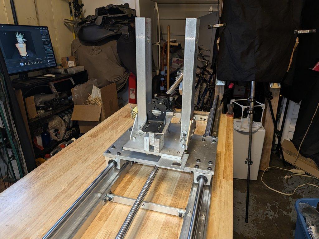
This stage brings together several major components: the base plate, uprights with gussets installed, and the boom drive motor.
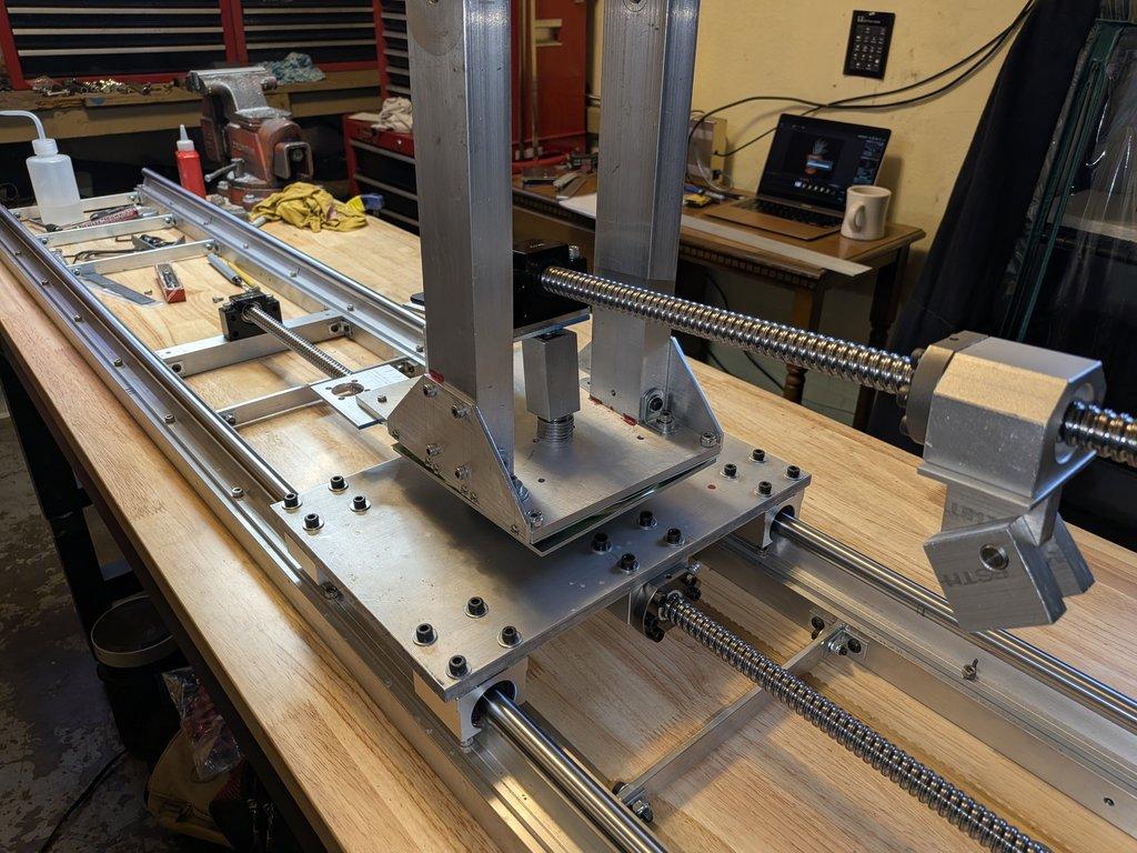
With these in place, the focus shifts to testing the fitment of the boom bearing block pivot and understanding how the system behaves as a whole.
This is where things start to feel like a machine—and where real constraints begin to show up.
⸻
Objective
The goal here is to confirm that the structural base and boom drive system align correctly and to test how the boom interface fits into the pivot and drive geometry.
⸻
Process
With the uprights repositioned and reinforced by gussets, the base plate now provides a stable platform for the rest of the system. The boom motor is mounted and aligned with the ball screw, completing the primary drive path.
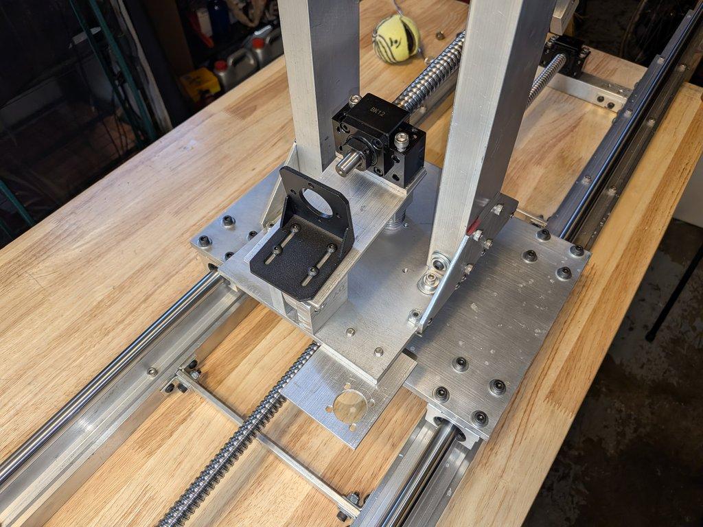
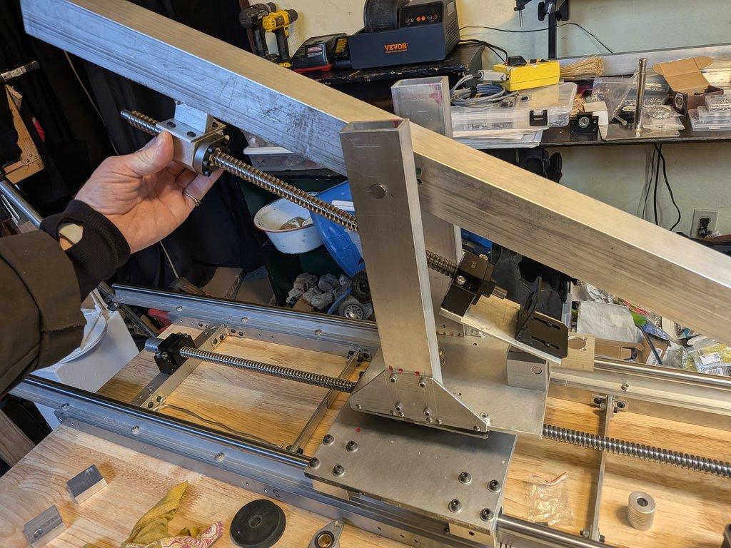
From there, the boom bearing block pivot is brought into position to test how it will attach and move within the system. This is not final assembly yet—it’s a fitment test, checking alignment, spacing, and range of motion.
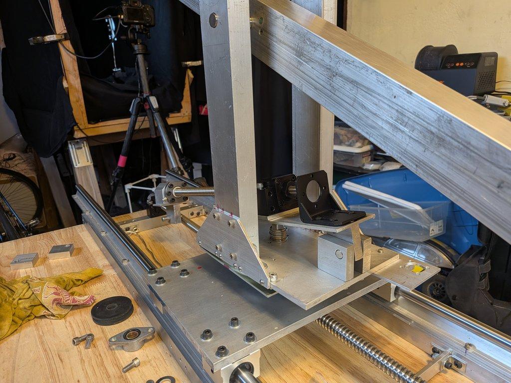
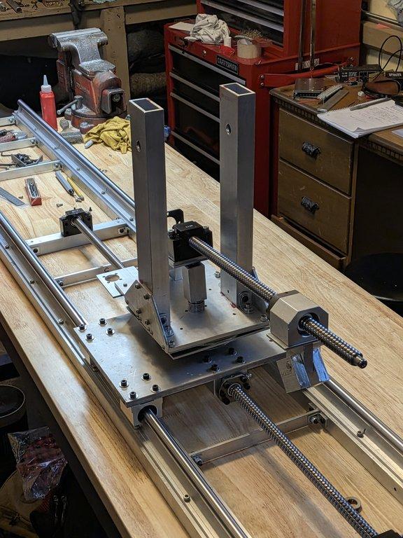
During this process, a key constraint becomes obvious: the ball screw extends far enough that it interferes with the boom arm’s movement. To allow proper travel, a portion of the boom arm needs to be removed or relieved.
⸻
Notes
This is one of those moments where the system tells you something you couldn’t fully predict on paper.
Everything is technically working:
- alignment is holding
- the drive system is connected
- the pivot geometry is behaving as expected
But the physical envelope—the actual space the parts occupy—introduces a conflict.
The ball screw length is correct for travel, but it overlaps with the boom arm’s path. That means the design needs to adapt.
This is a good example of why it’s important to test fit early. It’s much easier to adjust the boom arm now than to redesign the drive system later.
And again, this is destructive work. Removing material from the boom arm is a commitment, so it’s worth taking the time to:
- verify the interference
- check full range of motion
- make sure the modification solves the problem cleanly
⸻
LIMNMOCO Context
At this stage, the base system is doing real work:
- the uprights are rigid and supported
- the rotation base is established
- the boom drive is active and aligned
The boom interface is the last major piece to connect into this structure. Once it’s in place, the system will move as a complete unit.
This is where geometry, motion, and structure all intersect.
⸻
Why This Matters
This step highlights a core reality of physical builds:
Even when the mechanics are correct, space and movement can still conflict.
You’re not just designing motion—you’re designing where motion is allowed to exist.
Catching this now means:
- cleaner modifications
- better final geometry
- fewer surprises under load
Christopher Weinberg
Christopher Weinberg is the founder of LIMNMEDIA, where he develops motion control systems, production workflows, and educational tools focused on stop-motion and hybrid filmmaking. With over 15 years of experience in production, his work centers on making complex techniques more accessible through practical engineering and open development. He is currently building LIMNMOCO, a modular motion control system designed for flexible, real-world use.
No comments yet. Login to start a new discussion Start a new discussion