LIMNMEDIA - Ball Screw to Boom Linkage (and the Reality of Non-Linear Motion)
This stage focuses on the linkage that connects the ball screw to the boom arm.
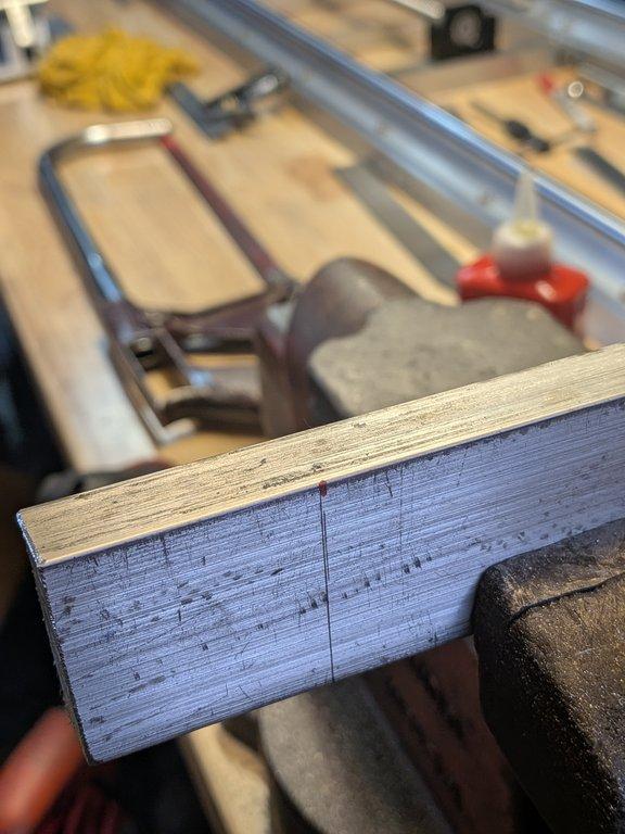
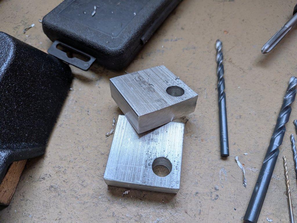
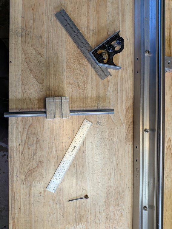
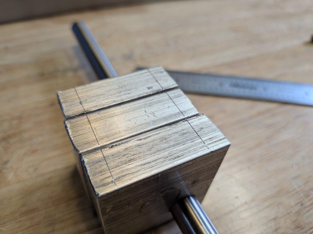
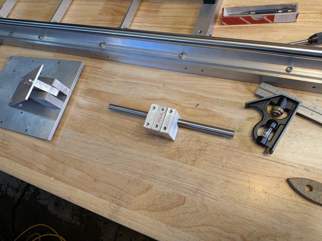
It’s a layered connection: the ball screw bearing block mounts to an adapter plate, which ties into the pivot blocks, which in turn connect to the boom arm.
At a glance, it’s a straightforward mechanical chain. But this is also where an important truth shows up: the motion being created is not linear—even though the input is.
⸻
Objective
The goal here is to transfer linear motion from the ball screw into controlled angular movement of the boom arm, allowing the camera to raise and lower.
At the same time, this step reveals a deeper challenge in the system: the mismatch between linear input and rotational output.
⸻
Process
The ball screw drives a bearing block that moves linearly along its axis. That motion is connected through an adapter plate into the pivot assembly. As the screw extends or retracts, it pushes or pulls on the pivot, causing the boom arm to rotate around its hinge
Mechanically, everything is doing exactly what it should. The parts are aligned, the motion transfers cleanly, and the system responds as expected when driven.
But the path of the boom is not straight—it’s an arc. That means the relationship between screw position and boom angle is constantly changing throughout the movement.
This is one of those moments where it’s worth slowing down and really looking at what’s happening.
The ball screw is doing exactly what it’s supposed to do—it’s moving in a straight line. But the boom isn’t. The boom is rotating around a pivot, so the end of it is traveling in an arc.
So right away, those two things don’t match.
As the screw moves, it’s pushing on the boom through that linkage, but the geometry is constantly changing. Sometimes it’s pushing in a way that’s really effective—small movement in the screw gives you a noticeable change in angle. Other times, the angle shifts and that same amount of movement barely changes the boom at all.
So even if the motor is running at a steady speed, the boom doesn’t move at a steady rate. It speeds up, slows down—it’s always changing across the range.
If you were to graph it, it wouldn’t be a straight line. It’s a curve.
And that’s not a mistake—that’s just what this kind of mechanism does.
This is where physical systems start to separate from digital ones. In the computer, everything is clean and linear unless you decide otherwise. Out here, it’s almost never linear to begin with.
So the goal isn’t to eliminate that—it’s to understand it well enough to work with it.
Later on, this gets handled in calibration. You map the real behavior of the system and compensate for it in software. It doesn’t make the mechanics perfect, but it makes the system predictable.
And honestly, that’s the real target: not perfect—just controlled.
⸻
Notes
This is where it’s important to pause and recognize something:
The system is not wrong, but it is not perfect either.
.
A linear actuator driving a rotating arm creates a compounded geometry. Early in the movement, a small change in screw position might produce a subtle change in angle. Later in the same movement, that same amount of screw travel could produce a much larger angular shift.
That means the system is inherently non-linear.
You can feel it even in manual testing:
- the motion isn’t uniform
- the response changes across the range
And that’s expected.
⸻
LIMNMOCO Context
This is one of the core challenges in motion control systems like this—especially in stop-motion.
Physically, you are always working with approximations:
- materials flex
- joints have tolerance
- geometry compounds
You build something that is close enough to ideal, but never perfectly ideal.
In this case, the non-linearity is addressed later in software. Calibration allows the system to map input values to actual positions, smoothing out the response and making it usable in practice.
But it doesn’t eliminate the underlying behavior—it just compensates for it.
⸻
Why This Matters
This is a really important distinction, especially today.
In digital systems, there’s an expectation of precision and exactness. Values map cleanly, motion is predictable, and everything behaves linearly unless told otherwise.
In physical systems, that’s almost never true.
So the goal shifts from:
making something perfect
to:
making something predictable and controllable
That difference is at the heart of stop-motion work. You’re constantly balancing between what is physically achievable and what is visually acceptable.
Getting “close enough” in the physical build—and then refining it through calibration—is not a compromise. It’s the process.
Christopher Weinberg
Christopher Weinberg is the founder of LIMNMEDIA, where he develops motion control systems, production workflows, and educational tools focused on stop-motion and hybrid filmmaking. With over 15 years of experience in production, his work centers on making complex techniques more accessible through practical engineering and open development. He is currently building LIMNMOCO, a modular motion control system designed for flexible, real-world use.
No comments yet. Login to start a new discussion Start a new discussion