LIMNMEDIA - Adapter Plate & Secondary Bolt Pattern
This stage continues the work on the large diameter XL pulley, adding a second 12-hole pattern on the opposite face and introducing the adapter plate that will carry the swing bearing.
With both faces of the pulley now active, this component becomes the central hub of the rotation system.
Objective
The goal here is to drill the second bolt circle on the pulley and mount a thinner adapter plate that will interface with the swing bearing. At the same time, this step reinforces the importance of accurate hole starting using proper center marks.
Process
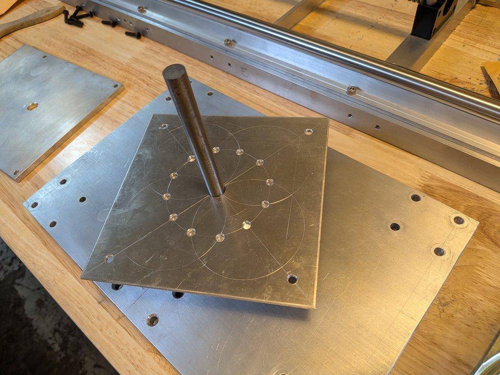
With the first bolt pattern complete, the pulley is flipped and the second 12-hole layout is transferred and drilled on the opposite face. As before, pilot holes are started carefully, followed by drilling to final size and tapping.
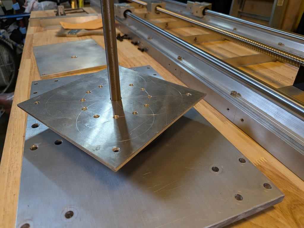
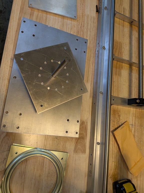
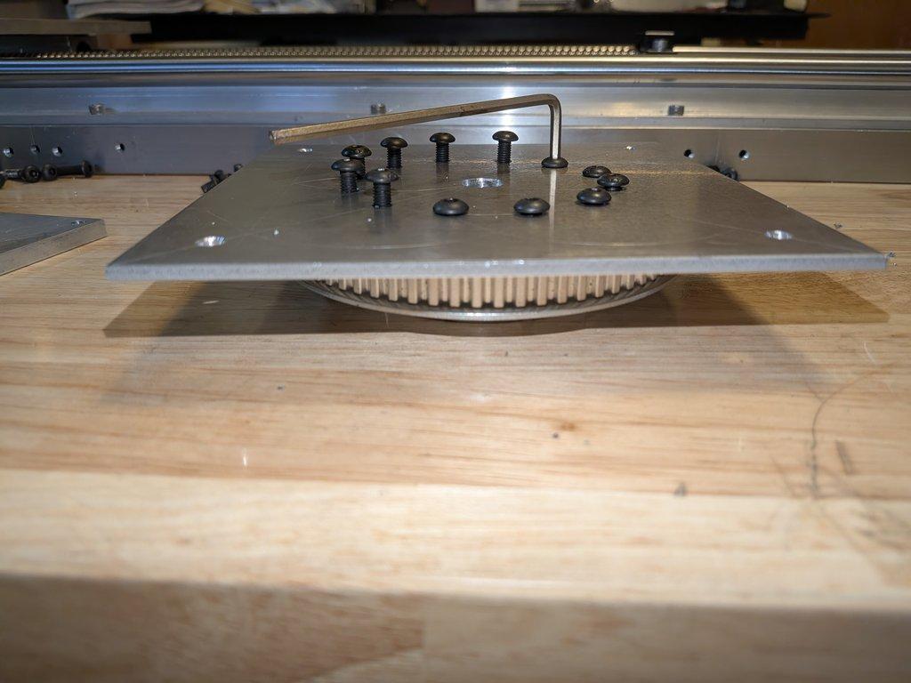
The adapter plate is then mounted to this new pattern. I chose a thinner stainless steel plate here to keep the overall stack height as low as possible. This becomes important later when fitting the swing drive pulley and belt system—the tighter this spacing, the easier it is to position the motor and maintain proper belt alignment.
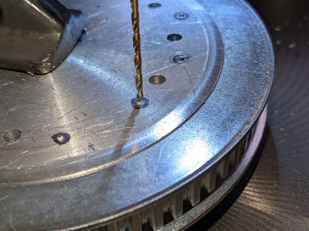
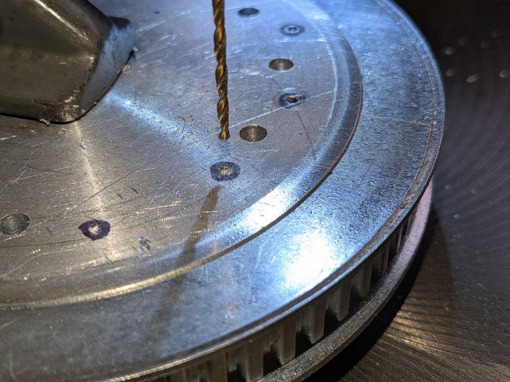
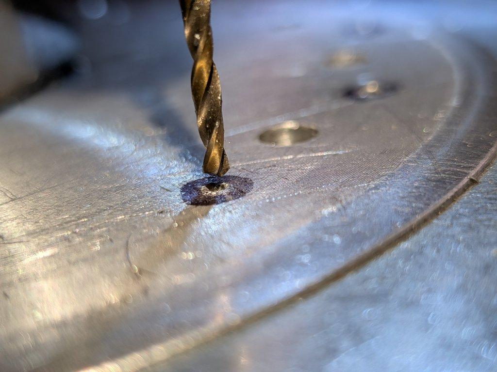
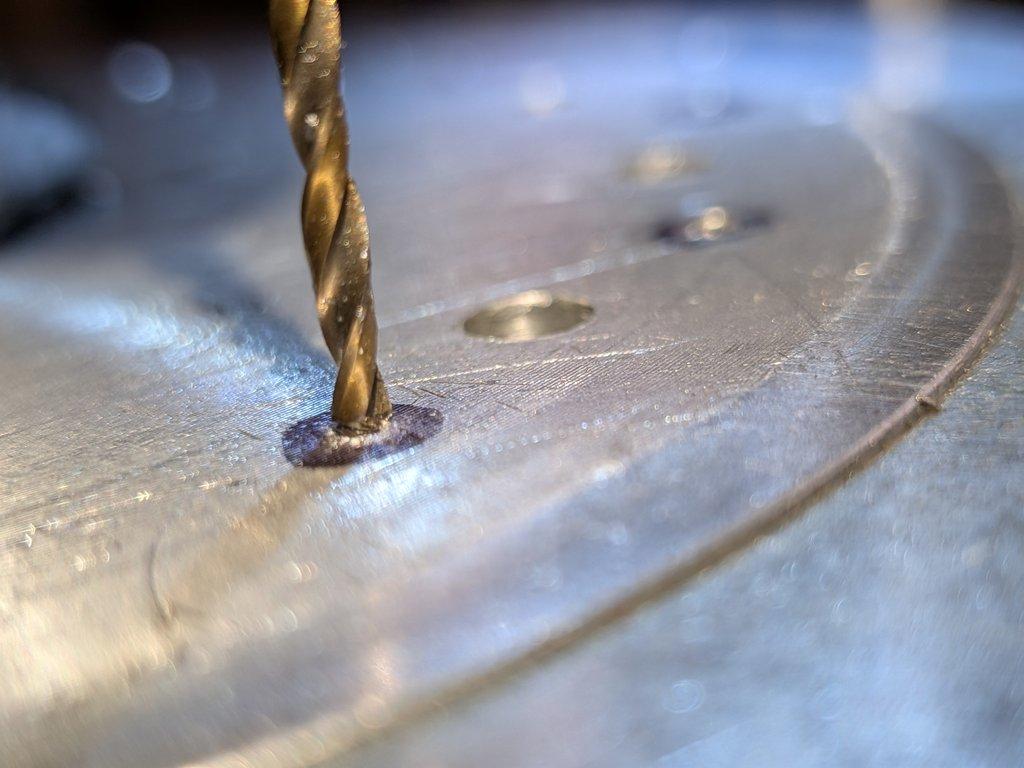
Throughout this process, the benefit of a proper center mark becomes very clear. The small dimple created by a center punch gives the tip of the pilot bit a place to register.
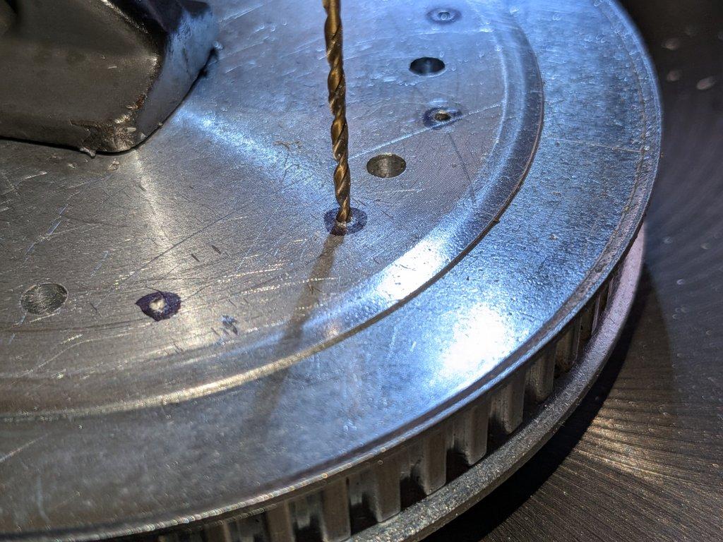
The bit naturally settles into that point, helping establish alignment before the drill even starts cutting. This makes it much easier to hold position while clamping and reduces the chance of the bit wandering off center.
Notes
This second bolt pattern has to stay consistent with the first, even though it’s on the opposite face. Any misalignment between the two sides will show up when the full stack is assembled.
The thinner adapter plate is a deliberate choice. While thicker material might feel more robust, it would push the swing drive components further apart and complicate belt routing. Keeping things compact here simplifies the mechanical layout downstream.
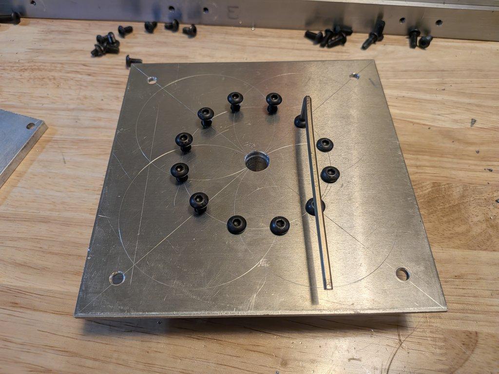
The contrast between marked holes and properly punched holes is also obvious at this stage. A clean center punch creates a repeatable starting point, while lighter marking methods require more interpretation and introduce small errors.
LIMNMOCO Context
At this point, the pulley is no longer just a drive component—it’s a connector between systems. One face ties into the sled plate, and the other now supports the adapter plate that will carry the swing bearing.
This effectively defines the core rotation interface of the crane:
- sled → pulley → adapter plate → swing bearing
Everything above the base will rotate through this stack.
Why This Matters
Stack height and alignment are critical in rotational systems. Adding unnecessary distance between components makes belt alignment harder and increases leverage forces on the system.
By keeping the adapter plate thin and the interfaces tight, the design stays compact and more controllable. Combined with accurate hole placement, this ensures that the rotation axis remains stable and predictable.
The center punch detail might seem small, but it directly affects the accuracy of every hole in the system. A good starting point leads to a straight hole, and straight holes lead to clean assembly.
Next Steps
The next phase will bring in the swing bearing itself and begin assembling the full rotation stage. From there, attention shifts to integrating the drive system—motor placement, pulley alignment, and belt routing.
Christopher Weinberg
Christopher Weinberg is the founder of LIMNMEDIA, where he develops motion control systems, production workflows, and educational tools focused on stop-motion and hybrid filmmaking. With over 15 years of experience in production, his work centers on making complex techniques more accessible through practical engineering and open development. He is currently building LIMNMOCO, a modular motion control system designed for flexible, real-world use.
No comments yet. Login to start a new discussion Start a new discussion